Do you want to make something cool for a party? This is the circuit for you.
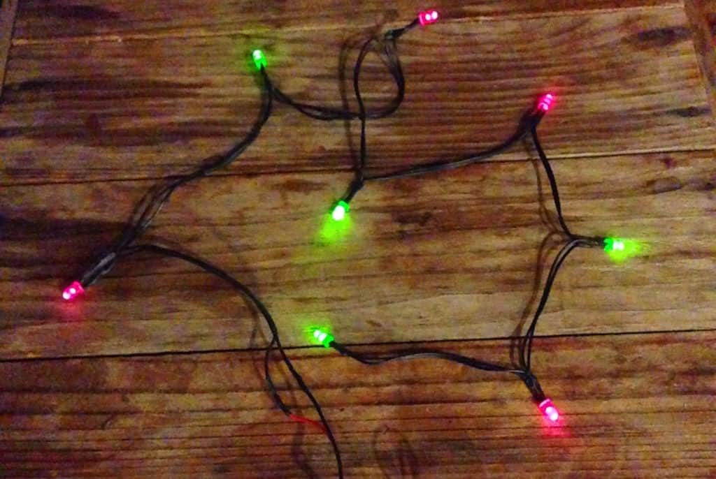
This is a simple way of blinking many lights at the same time. If you add the LEDs to a long wire, you can hang them in a window or use them to decorate a tree.
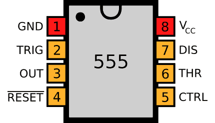
The circuit uses a 555 Timer, which is a classic integrated circuit that makes is really easy to make things turn on and off repeatedly. R1, R2, and C1 set the blinking speed while R3 sets the current that goes out to the LEDs.
Here’s the pinout of the 555 timer IC:
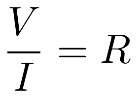
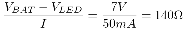
You can add or remove LEDs by changing the value of the resistor R3. For example, if each LED needs 10mA and you want to use 5 LEDs, you need 5 x 10mA = 50 mA through the resistor. You can use Ohm’s law to figure out the correct resistor value:
In our 5-LED example, that translates to:
Note: A standard 555 Timer can only give out up to 100 mA in total.
The Circuit Diagram
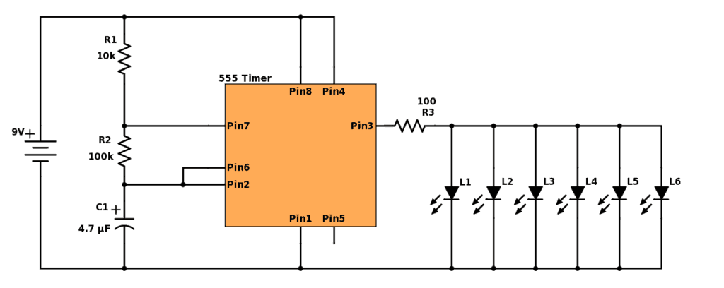
Find the components used in the table below.
| Part | Value | Note |
|---|---|---|
| R1 | 10 kΩ | Standard Resistor |
| R2 | 100 kΩ | Standard Resistor |
| R3 | 100 Ω | Standard Resistor |
| C1 | 4.7 μF | Polarized Capacitor |
| L1 to L6 | Red, yellow or green | Standard output light-emitting diode |
| U1 | NE555 | 555 Timer IC |
Are You Stuck?
Let me know your questions and comments in the comment field below
I have added 4 LEDs to the output resistor. But only one LED is glowing..I am unable to figure out. Can you let me know possible reasons ?
Are you sure you have them connected in the correct direction? If yes, are they of the same type? If yes to both, it’s very likely that the ones that are not glowing are broken. Test them one by one with a 1k resistor to check.
I have built tried this circuit three times, and three times I have blown 6 LEDs. I tried increasing the resistor each time, the last time to 1M. I think the trouble is how I have everything connected, but for the life of me I can’t figure it out. Can you post or email me a diagram of how you connected it? I don’t want to fry any more LEDs! Thanks so much 🙂
This sounds like a problem with the connection of the resistor at the output. I don’t have a diagram, but I’ll see if I can make one soon. I’ll update here with link once I do.
If you want, I could take a look at your connections. Just take a few photos of your circuit and upload (for example here: https://pasteboard.co/) and paste the link here.
Should R1 connect PIN 7 and PIN 8, or should it connect PIN 7 to +? Or should R1 and PIN 8 share a row, which is connected to +? I can’t picture how to connect the parts when there isn’t a clear solid dot to indicate the endpoint. I think seeing an example of a layout would help me understand the connections. Thanks! Also, the 6 LEDs that I’m using each draw 20MA. That would mean R3 should be in the neighborhood of 70 Ohms, assuming a 9V battery, right? But all my EDs kept blowing.