Creating sound is fun! In this circuit, you’ll build a musical instrument. It will have four buttons for playing different tones.
The circuit uses a 555 Timer to create a voltage that goes on and off repeatedly. To make sound you need a voltage that turns on and off repeatedly. But, you need the voltage to turn on and off really fast. Like a few thousand times a second.
The value of capacitor C1, resistor R1, and the resistance between pin 6 and 7 will set the tone of the sound. The pushbuttons have resistors in between them so that the resistance between pin 6 and 7 will be different depending on which button you push. This results in a different tone being played for each of the buttons.
If you want more than four buttons on your instrument, you can add more pushbuttons and resistors.
Here’s a video of the circuit I made:
The Circuit Diagram
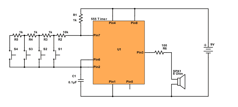
Find the components used in the table below.
| Part | Value | Note |
|---|---|---|
| R1 | 1 kΩ | Standard resistor |
| R2 | 10 kΩ | Standard resistor |
| R3-5 | 1 kΩ | Standard resistor |
| R6 | 100 Ω | Standard resistor |
| C1 | 0.1 μF | Non-polarized capacitor |
| U1 | NE555 | 555 Timer IC |
| S1-S4 | Momentary ON | Tactile Pushbutton |
| SPK1 | 8 Ω | Mini speaker |
Are You Stuck?
Let me know your questions and comments in the comment field below
Wow, this was a very interesting project. I tried following the circuit diagram to no avail, then came here to watch the video in hopes of getting a better idea of how to connect the components.
After I was still having issues, I looked on YouTube and found this (sharing for potential future visitors: https://www.youtube.com/watch?v=Ig_6o9bMABA).
Me being me, I attempted to reverse engineer why I was failing, only to find out that my 555 timer was the issue…
Still a tad confused on how to accurately read circuit diagrams, which I see as the biggest road block for me during my current phase of understanding projects. Regardless though, still having fun along the way.
Two more observations:
1) The fact that there is no 10uF Capacitor in the circuit diagram but there is one present in the video (both the video on this page and the one on the YouTube video) was VERY confusing;
2) The 10k Ohm resistor connect pin 7 to S1 causing each button to emit the same sound, whereas following the YouTube videos guidance, a 4.7k Ohm resistor caused the sound to vary.
Just sharing/documenting my findings just in case anyone runs into anything similar that I may have.
When I started this chapter, I realized that I lost the speaker that came with the component kit. I will need to buy another one online. Will any 8 ohm speaker work as a replacement?
Yes, as long as it’s not too big. So get a small speaker, like 1W or less, to be sure. Or you can use a buzzer.