Do you want to keep people from stealing cookies from your cookie jar? Or maybe you have some other type of box that you don’t want people to snoop around in. Then this circuit is for you.
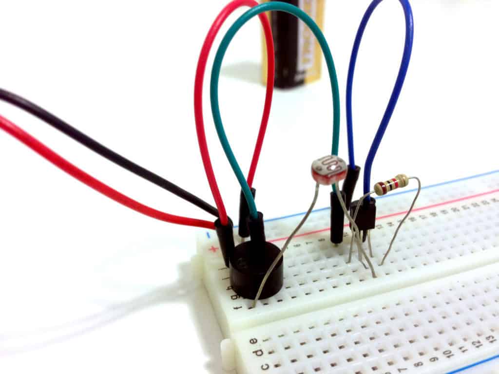
This circuit stays quiet when it’s in a dark place, such as a cookie jar with the lid on. But once you open the lid and let light inside, the circuit turns on the buzzer that creates an alarm sound that should scare off the cookie thieves.
Check out the video below for my version of the circuit:
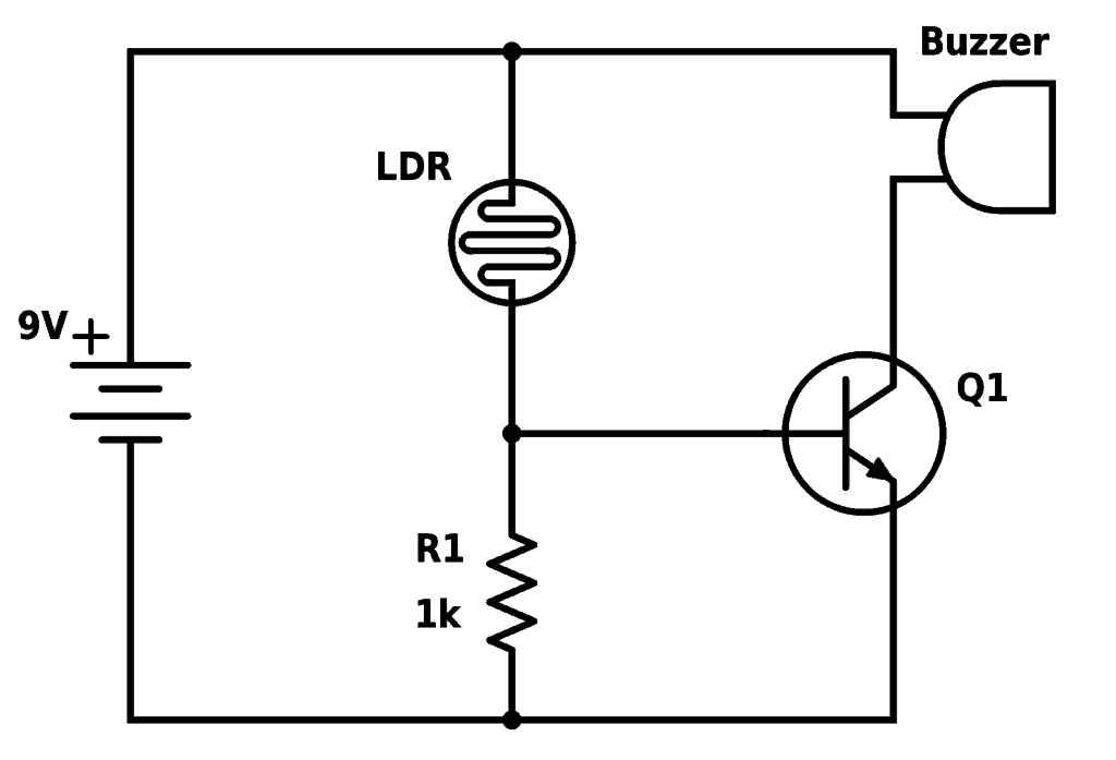
The Circuit Diagram
Find the components used in the table below.
| Part | Value | Note |
|---|---|---|
| LDR | ~200kΩ | Light-dependent resistor (photoresistor) with around 5-10kΩ resistance in light and around 200kΩ or more in dark |
| Q1 | BC547 | Any general purpose NPN transistor will work |
| R1 | 1 kΩ | |
| Buzzer | Active buzzer that works with 9V |
Are You Stuck?
Let me know your questions and comments in the comment field below.
Hi, so I am really hoping to get good top down photos of these circuits, that would really be helpful, maybe if you had those upon request but I realized a question that might be able to illuminate things for me: what happens at a junction? on a breadboard will a junction have one end of one component being “connected” via a grid line to TWO components? this is what I am struggling with, and I feel like if I can figure that out I will much better be able to read schematics…. obv Im not articulating this so great but hopefully you can help explain this, thanks so much!!! and: ENJOY YR TRIP!!!
Hey Joshua,
I don’t have good top-down photos, unfortunately. One reason is that it’s hard to take good photos because of the jumper wires. But another reason is that I really want the reader to understand the things you are trying to understand now – because then you’re free. Then you can build almost any circuit you find online or in other books without any more instructions than the circuit diagram.
As for the junction:
In the circuit diagram, a junction means that the pins that go to that junction should be connected. And “connected” means that the metal of one pin needs to touch the metal of the other pins – directly or through something made of metal.
On the breadboard, you have lots of rows of 5 holes. Inside the breadboard there is a piece of metal connecting these 5 holes. So if you want to connect a junction of three pins, you plug those three pins into the same row – and the metal inside the breadboard will connect them.
Does that make sense?
Best,
Oyvind
Hi, we are building the cookie jar circuit. We can get the buzzer to stay on but we cant get the LDR to work. We tried using 2 and we tried increasing the resistor. Is there a website you know that teaches how to read circuits? I am a homeschool teacher and I have been building breadboard circuits with my student all year. We are struggling with reading diagrams, maybe it’s called Fritzing?
Hi Quinn, we teach electronics, how to read circuit diagrams included, here at Ohmify =) If you’ve connected the above circuit as shown in the schematics and the buzzer stays on, it means that the value of the photoresistor is low. In dark it should get high and the buzzer should turn off. If making it dark does not work, then try a lower value for R1, for example 100 or 470 ohm.