One of the first things I wanted to learn in electronics as a kid was how to blink a light.
There are several ways of doing this, but this circuit is probably the easiest way to do it when it comes to the number of components. You only need three components for the blinking part. Then the resistor and LED to be blinked of course.
Here’s a video of the circuit I made:
The Circuit Diagram
The numbers next to each pin in the diagram represent the pin number on the integrated circuit. Click here for the pinout of the 74C14 IC.
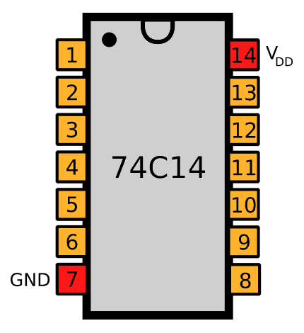
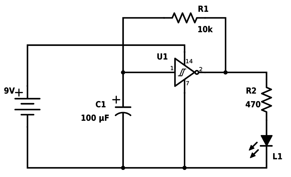
Find the components used in the table below.
| Part | Value | Note |
|---|---|---|
| U1 | 74C14 | Hex Schmitt Trigger Inverter |
| C1 | 100μF | Polarized capacitor |
| R1 | 10 kΩ | Standard Resistor |
| R2 | 470 Ω | Standard Resistor |
| LED | Standard output light-emitting diode |
Are You Stuck?
Let me know your questions and comments in the comment field below
Hi, love the book. Got it for my kids but have been using it more for myself.
I Have a question about project 5. The led in my circuit just comes on once and then shuts off, no blinking. Ive checked my connections but can’t seem to diagnose the fault. Would you be able to help me?
Thank you!
Hey Alfred, glad you liked the book! Are you using the 74C14? Or a differect one like 74HC14 or CD40106? That can impact things. But the first thing to try could be to swap the R2 with a larger resistor. For example 10k. If it doesn’t light up at all, try something smaller, my 1-5k.
This resistor decides how much current that goes to the LED. Which means that the chip has to provide the current. Some chips can’t provide as much current as the 74C14 and won’t work properly with the 470 resistor.
Hello,
Upon following the circuit diagram and the video above, I cannot get my LED to flash – it just constantly stays on.
The main thing I am noticing is that the chip itself is 74C14N vs 74C14, but the SKU matches what’s listed in the book. Could the inverter be the issue?
I managed to figure it out, saw your YouTube channel. On there, you mentioned x2 10K Ohm transistors and that worked. The book calls for x1 10K and x1 470 Ohm, and for some reason this wasn’t working.
Was able to play with the capacitor a bit (4.7, 10, 100) to observe the blinking speeds.
I am fairly fresh to circuitry and such but this has been fun for sure. Got the ebook a bit ago but just got around to reading through it.
One recommendation I have is that, unless I missed it, there is no dicussion about how to read the circuit diagrams. Going through the book and reading some comments on this website helped me stitch some pieces together, but I don’t get the solid block dots vs empty white dots and such.
Nonetheless, learning along the way and having fun!
I’m glad you figured it out – and thanks for the feedback!