In this circuit, you’re going to build a touch sensor. You’ll create a touch-pad from two uninsulated wires. If you don’t have any wire, you could clip off a bit of the legs of one of the components.
These are the names of the transistor pins:
- Top pin: Collector
- Bottom pin: Emitter
- Left pin: Base
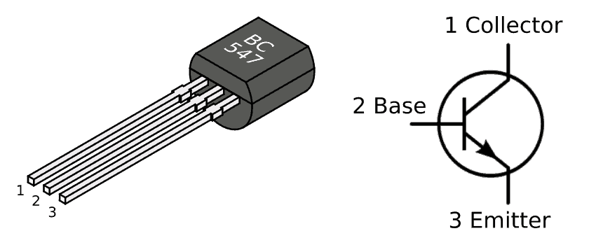
Note that if you are using a different transistor than the BC547, the pins may be arranged differently.
Here’s a video of the version I built. I needed to wet my finger bit to get the LED to turn on:
The Circuit Diagram
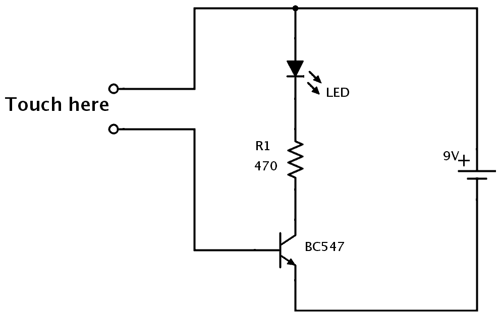
Find the components used in the table below.
| Part | Value | Note |
|---|---|---|
| R1 | 470 Ω | A standard resistor |
| LED | Red/Yellow/Green | Standard output light-emitting diode |
| Q1 | BC547 | General-purpose NPN transistor |
Are You Stuck?
Let me know your questions and comments in the comment field below